Achieving High Availability using Cisco VSS
Introduction
Network operators increase network reliability by configuring switches or SIP-400 CWAN line cards in redundant pairs and by provisioning links to the redundant pairs. Redundant network elements and redundant links can add complexity to network design and operation. Virtual switching simplifies the network by reducing the number of network elements and hiding the complexity of managing redundant switches and links. A VSS combines a pair of Catalyst 6500 series switches or SIP-400 CWAN line cards into a single network element. The VSS manages the redundant links, which externally act as a single port channel.
The VSS simplifies network configuration and operation by reducing the number of Layer 3 routing neighbors and by providing a loop-free Layer 2 topology.
Virtual Switching System:
An access switch connects to both chassis of the VSS using one logical port channel. The VSS manages redundancy and load balancing on the port channel. This capability enables a loop-free Layer 2 network topology. The VSS also simplifies the Layer 3 network topology because the VSS reduces the number of routing peers in the network.
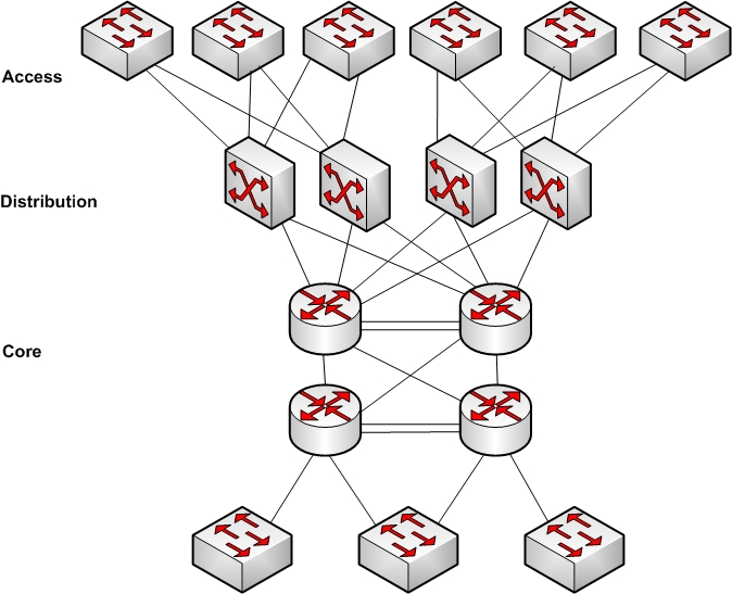
Figure1 : Typical Network Design
VSS Active and VSS Standby Chassis
When you create or restart a VSS, the peer chassis negotiate their roles. One chassis becomes the VSS active chassis, and the other chassis becomes the VSS standby.
The VSS active chassis controls the VSS. It runs the Layer 2 and Layer 3 control protocols for the switching modules on both chassis. The VSS active chassis also provides management functions for the VSS, such as module online insertion and removal (OIR) and the console interface.
The VSS active and VSS standby chassis perform packet forwarding for ingress data traffic on their locally hosted interfaces. However, the VSS standby chassis sends all control traffic to the VSS active chassis for processing.

Figure2: VSS View.
Virtual Switch Link
For the two chassis of the VSS to act as one network element, they need to share control information and data traffic.
The virtual switch link (VSL) is a special link that carries control and data traffic between the two chassis of a VSS. The VSL is implemented as an Ether Channel with up to eight links. The VSL gives control traffic higher priority than data traffic so that control messages are never discarded. Data traffic is load balanced among the VSL links by the Ether Channel
load-balancing algorithm.
VSS Functionality
The following sections describe the main functionality of a VSS:
Redundancy and High Availability:
In a VSS, supervisor engine redundancy operates between the VSS active and VSS standby chassis, using stateful switchover (SSO) and nonstop forwarding (NSF). The peer chassis exchange configuration and state information across the VSL and the VSS standby supervisor engine runs in hot VSS standby mode.
The VSS standby chassis monitors the VSS active chassis using the VSL. If it detects failure, the VSS standby chassis initiates a switchover and takes on the VSS active role. When the failed chassis recovers, it takes on the VSS standby role.
Packet Handling:
The VSS active supervisor engine runs the Layer 2 and Layer 3 protocols and features for the VSS and manages the DFC modules for both chassis. The VSS uses VSL to communicate protocol and system information between the peer chassis and to carry data traffic between the chassis when required.
System Management:
The VSS active supervisor engine acts as a single point of control for the VSS. For example, the VSS active supervisor engine handles OIR of switching modules on both chassis. The VSS active supervisor engine uses VSL to send messages to and from local ports on the VSS standby chassis.
Interface Naming Convention:
In VSS mode, interfaces are specified using the switch number (in addition to slot and port), because the same slot numbers are used on both chassis. For example, the interface 1/5/4 command specifies port 4 of the switching module in slot 5 of switch 1. The interface 2/5/4 command specifies port 4 on the switching module in slot 5 of
switch 2.
Software Features:
With some exceptions, the VSS has feature parity with the standalone Catalyst 6500 series
switch. Major exceptions include:
- In software releases earlier than Cisco IOS Release 12.2(33)SXI2, the VSS does not support IPv6 unicast or MPLS.
- In software releases earlier than Cisco IOS Release 12.2(33)SXI, port-based QoS and port ACLs (PACLs) are supported only on Layer 2 single-chassis or multi chassis Ether Channel (MEC) links. Beginning with Cisco IOS Release 12.2(33)SXI,
port-based QoS and PACLs can be applied to any physical port in the VSS, excluding ports in the VSL. PACLs can be applied to no more than 2046 ports in the VSS. - In software releases earlier than Cisco IOS Release 12.2(33)SXI4, the VSS does not support supervisor engine redundancy within a chassis.
- Starting in Cisco IOS Release 12.2(33)SXI4, the VSS does support supervisor engine redundancy within a chassis.
- The VSS does not support Lawful Intercept.
Failed Chassis Recovery
If the VSS active chassis or supervisor engine fails, the VSS initiates a stateful switchover (SSO) and the former VSS standby supervisor engine assumes the VSS active role. The failed chassis performs recovery action by reloading the supervisor engine.
If the VSS standby chassis or supervisor engine fails, no switchover is required. The failed chassis performs recovery action by reloading the supervisor engine.
For additional information about VSS, Refer your Cisco hardware documentation or www.cisco.com
You can also keep up to date with current trends and technology by visiting Data Centre Talk where we keep you informed on important changes as they occur.